SunVena Solar Blog

Residential Solar News, Insights & Resources

What Is a Chamfering Cutter and How Does It Work?

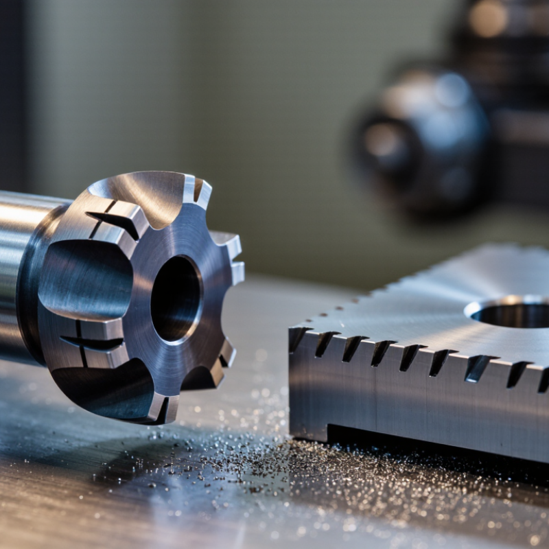
A Chamfering Cutter is a cutting tool designed to remove a sharp edge from a workpiece. It creates a sloped surface, known as a chamfer, along a hole, outside corner, or machined profile. This small feature can improve assembly, reduce burrs, and make metal parts safer to handle. It may also help guide screws, pins, or bearings into position.

The tool works by rotating against the workpiece at a controlled speed and feed rate. Its angled cutting edges remove a measured amount of material during contact. For example, a machinist may use a countersink-style cutter to create a clean bevel around a drilled hole. On a milling machine, an indexable Chamfering Tool can produce consistent edge details across several parts. Tool diameter, cutting angle, material hardness, and machine rigidity all affect the result. Small changes matter.

The process is not foolproof. Poor alignment can create an uneven bevel, while excessive feed pressure may leave chatter marks or damage the edge. I have found that checking the first component with calipers or a chamfer gauge prevents repeated errors. Coolant, tool sharpness, and workholding also deserve attention. A drawing may specify a 1 mm chamfer, but manufacturing conditions can change its appearance. This guide explains common cutter designs, working principles, setup methods, and practical inspection steps. It also considers limitations that are easy to overlook. A neat chamfer is useful, but it is not automatically a sign of perfect machining.
What Is a Chamfering Cutter and How Does It Work?

What Is a Chamfering Cutter?

A chamfering cutter is a cutting tool designed to create a sloped edge on a workpiece. It removes a small amount of material from a sharp corner. The result is a cleaner transition between two surfaces. Chamfers can reduce burrs, protect edges, and help parts enter holes more easily. Common chamfer angles include 45 degrees, although the required angle depends on the drawing and application. Cutter diameter, cutting depth, and workpiece material also affect the final result.

During machining, the rotating cutter contacts the corner at a controlled feed rate. Its angled cutting edges shear away material rather than pressing it flat. As the cutter moves along the edge, it produces a consistent bevel. On a metal part, the process may create small chips and heat. The edge stays clean. However, performance depends on correct tool alignment and stable workholding. Excessive feed can leave marks or damage the corner.

In a workshop, an operator may use a caliper to check the chamfer width after cutting. A depth setting that looks accurate can still produce a visible variation. Cutting fluid may improve surface quality, but its use depends on the material and machine setup. A perfect chamfer is not automatic. Small errors matter. Tool wear, vibration, and uneven stock can change the result, so inspecting several points remains a sensible practice.

Key Parts and Cutting Features of a Chamfering Cutter

A chamfering cutter removes a sharp edge and creates a controlled bevel on a workpiece. Its performance depends on several small parts working together.

The shank holds the cutter in a spindle or tool holder. The cutter body carries the flutes, which guide chips away from the cutting zone. Each flute has a cutting edge, rake face, and relief face. The rake face directs the chip, while the relief face prevents rubbing against the finished surface. Carbide versions are widely used because they resist wear at higher cutting speeds. Grand View Research reported that carbide tools represented over half of global cutting-tool revenue in 2023, reflecting their industrial importance.

The included angle defines the chamfer profile. Common settings include 45 degrees, but production work may require 30 or 60 degrees. A pilot can guide the tool inside a hole, while a countersink-style point cuts without one. Feed rate, spindle speed, and tool projection control heat, vibration, and edge life. The U.S. Cutting Tool Institute’s industry reports consistently identify tool life and dimensional control as major purchasing concerns. A 0.02-millimeter error can visibly change a small chamfer. That is the trap.

In practice, I check the edge under magnification before blaming the machine. Uneven flute loading may come from poor workholding, not cutter failure. Coolant helps, but it cannot correct excessive feed. The report data supports carbide use, yet real results still depend on material, rigidity, and inspection discipline.

How a Chamfering Cutter Removes Material

What Is a Chamfering Cutter and How Does It Work?

How a Chamfering Cutter Removes Material

A chamfering cutter creates an angled edge by removing a narrow strip of material. Its cutting edges meet the workpiece at a controlled angle, rather than cutting straight down. As the spindle rotates, each flute shears a small chip from the corner. The machine then follows a programmed path around the hole, edge, or profile.

The result depends on axial depth, radial engagement, feed rate, and tool geometry. A shallow pass usually produces a cleaner edge and smaller cutting load. Excessive engagement can create chatter, heat, or a torn surface. Chips should leave the cutting zone freely. Compressed air or suitable coolant often helps, especially with sticky alloys.

The 2024 U.S. Cutting Tool Consumption report from AMT and USCTI recorded approximately 2.6 billion dollars in annual cutting-tool shipments. That figure shows the scale of industrial machining, but it does not guarantee good chamfer quality. Setup still matters more than many operators expect. A machinist should inspect the first part with a gauge or optical comparator, then check the edge under magnification.

A practical mistake is treating every chamfer like a cosmetic detail. A sharp edge can interfere with assembly, while an oversized chamfer can reduce contact strength. Tool wear also changes the effective angle. The first pass may look perfect. The twentieth may not. Even manufacturer cutting data needs adjustment when rigidity, material hardness, or workholding differs.

How a Chamfering Cutter Removes Material

For a 45° chamfer, the removed cross-section is approximately a right triangle. Its area is calculated as A = ½ × c², where c is the chamfer width in millimeters. The values below represent material removed per 1 mm of cutting-edge length.

Common Types of Chamfering Cutters

A chamfering cutter removes material from an edge at a controlled angle. It creates a sloped surface instead of a sharp corner. This improves part handling and reduces edge damage during assembly. Small edges matter. The cutter usually works through rotary motion, while the workpiece or tool follows a programmed path. Cutting depth determines the chamfer width.

The 45-degree single-angle cutter is the most common choice for general edge preparation. It suits many steel, aluminum, and plastic components. A multi-angle cutter offers greater flexibility when drawings specify unusual angles. An adjustable model can produce different chamfer widths, but it demands careful setup.

Indexable chamfering cutters use replaceable inserts and support repeated production work. They can reduce downtime, although insert seating must remain accurate. Countersink cutters create conical recesses inside holes and can chamfer hole entrances neatly. They are not a complete substitute for edge chamfering tools.

Deburring cutters handle light edge breaking after drilling, milling, or turning. They remove burrs quickly, but heavy cuts may damage their small cutting edges. In shop practice, cutter diameter, flute geometry, spindle speed, and workpiece hardness all affect the result. A rigid setup usually produces a cleaner surface. The 45-degree option is common, not universally correct. Checking the drawing and measuring the finished edge remains essential. Even experienced operators sometimes choose a cutter by habit, then discover the chamfer is wider than expected.

Applications and Selection Factors for Chamfering Cutters

What Is a Chamfering Cutter and How Does It Work?

A chamfering cutter removes material from an edge at a controlled angle. A common 45-degree chamfer softens sharp corners and removes burrs. During cutting, the tool rotates while its angled flutes contact the workpiece. The result is a clean edge that improves handling and assembly. Chamfers can also guide bolts, support countersunk features, or prepare edges for welding. In practical machining, the cutter must remain stable. Vibration can create uneven lines, especially on thin plates or interrupted surfaces.

Applications and selection factors matter more than appearance alone. Choose the cutter angle according to the drawing and assembly requirement. Check the workpiece material, cutting diameter, flute geometry, and machine rigidity. A sharp cutter suits aluminum, while tougher materials may require stronger edge support. Cutting speed and feed should follow the tool maker’s data, then be adjusted carefully. Too much feed can leave ridges. Too little feed may cause rubbing and heat. The “best” cutter on paper may still perform poorly on an unstable setup.

Tips: Inspect the edge under bright light after machining. A small burr often signals excessive runout, a worn edge, or incorrect feed. Secure thin parts firmly, and test the setting on scrap material. Do not chase a perfect finish blindly; function, fit, and repeatability usually matter more.

What Is a Chamfering Cutter and How Does It Work? - Applications and Selection Factors for Chamfering Cutters
Reference table for cutter geometry, machining applications, and selection guidelines
Cutter Type or Factor Key Characteristics Typical Applications Selection Guidance
Single-angle chamfering cutter Uses one primary angled cutting surface to create a straight chamfer along an external or internal edge. Edge breaking, deburring, part preparation, and general-purpose milling. Choose the cutter angle and diameter according to the required chamfer width, access, and workpiece geometry.
Included-angle geometry A 90° included angle commonly produces a 45° chamfer on the workpiece when both sides are symmetrical. Standard edge chamfers, countersink-style features, and general edge finishing. Confirm whether the drawing specifies the included angle or the angle measured from the workpiece surface.
30° to 45° cutting angle Creates a relatively shallow chamfer and is useful where a broad, low-profile edge break is required. Large edge breaks, visual finishing, clearance transitions, and selected aerospace or fabrication features. Check tool clearance carefully; a shallow angle may require more radial space to achieve the target chamfer width.
60° to 90° cutting angle Produces a steeper chamfer and can reach the specified edge size with less lateral tool movement. Small edge breaks, hole-mouth chamfers, countersinking, and parts with restricted access. Use when tool access is limited, but verify that the resulting chamfer angle matches the engineering drawing.
Solid carbide cutter High stiffness, wear resistance, and cutting-edge stability; suitable for rigid machine setups and higher cutting speeds. Hardened steels within the tool’s rating, stainless steels, cast iron, nonferrous alloys, and production milling. Select based on workpiece hardness, rigidity, flute design, and manufacturer-recommended cutting data.
High-speed steel cutter Generally more tolerant of interrupted cuts and lower machine rigidity, but normally operates at lower speeds than carbide. General maintenance, low-volume work, manual milling, and softer materials. Consider HSS when impact resistance, lower cost, or flexible low-speed machining is more important than maximum productivity.
Indexable chamfering cutter Uses replaceable inserts, allowing worn cutting edges to be changed without replacing the complete cutter body. Repeated production chamfering, large-diameter edge work, and applications requiring predictable insert replacement. Verify insert angle, corner preparation, clamping security, and the available cutting diameter range.
Number of flutes More flutes can increase feed capacity, while fewer flutes provide more chip space and may improve performance in ductile materials. The correct choice depends on material, chip formation, coolant use, and required productivity. Use the tool maker’s chip-load data; do not select flute count independently of spindle speed and feed rate.
Workpiece material Material hardness, abrasiveness, thermal conductivity, and tendency to form built-up edge affect tool life and surface finish. Common materials include aluminum, copper alloys, steels, stainless steels, cast iron, and engineering plastics. Match substrate, coating, rake geometry, and cutting parameters to the specific material family.
Chamfer width The required width is controlled by cutter angle, radial or axial depth of cut, and the original edge condition. Deburring may require a small edge break, while assembly lead-ins and visual features may require a larger chamfer. Use a test cut or calculation to confirm the actual chamfer width, especially when the angle is not 45°.
Machine and setup rigidity Tool overhang, spindle condition, workholding, and machine rigidity influence vibration, burr formation, and dimensional consistency. CNC milling, machining centers, manual mills, and multi-axis setups. Minimize overhang, secure the workpiece, and reduce speed or engagement if chatter appears.
Coolant and chip evacuation Effective chip removal reduces recutting, heat accumulation, built-up edge, and surface damage. Long chamfering passes, aluminum machining, stainless steel, and deep or partially enclosed features. Use air blast, mist, or flood coolant according to the material and tool guidance; avoid chip recutting.
Practical note: Cutting speed, feed per tooth, depth of cut, and coolant selection are application-specific. Always confirm the final parameters with the cutter manufacturer’s technical data and validate the chamfer against the part drawing.