SunVena Solar Blog
Residential Solar News, Insights & Resources
2026 Best Litz Wire for High Frequency Applications?
Choosing the best litz wire for high-frequency applications in 2026 is not simply a matter of comparing brands. The right choice depends on operating frequency, current, temperature, and the winding geometry. At higher frequencies, current tends to concentrate near conductor surfaces, increasing resistance and heat. Properly insulated, transposed strands can help manage these effects, but litz wire is not automatically the best solution for every coil.
A transformer designer may prioritize low AC resistance and compact winding space. A motor or induction-heating engineer may care more about flexibility, insulation durability, and thermal performance. Strand diameter matters because it relates to skin depth, while strand count and overall bundle size affect current capacity and fit. Details matter. Check the manufacturer’s specifications for strand construction, insulation class, temperature limits, and recommended frequency range. Then compare those claims with the actual waveform and operating conditions, not just a headline rating.
This guide will explain how to assess litz wire options, read technical data, and match cable construction to common high-frequency uses. It will also consider practical trade-offs, including cost, termination difficulty, and winding space. A carefully selected wire can still disappoint if the coil layout or cooling is poor. That is easy to overlook. Since published ratings may rely on specific test setups, verify critical performance in the intended assembly whenever possible. The aim is a defensible choice, not a universal winner.
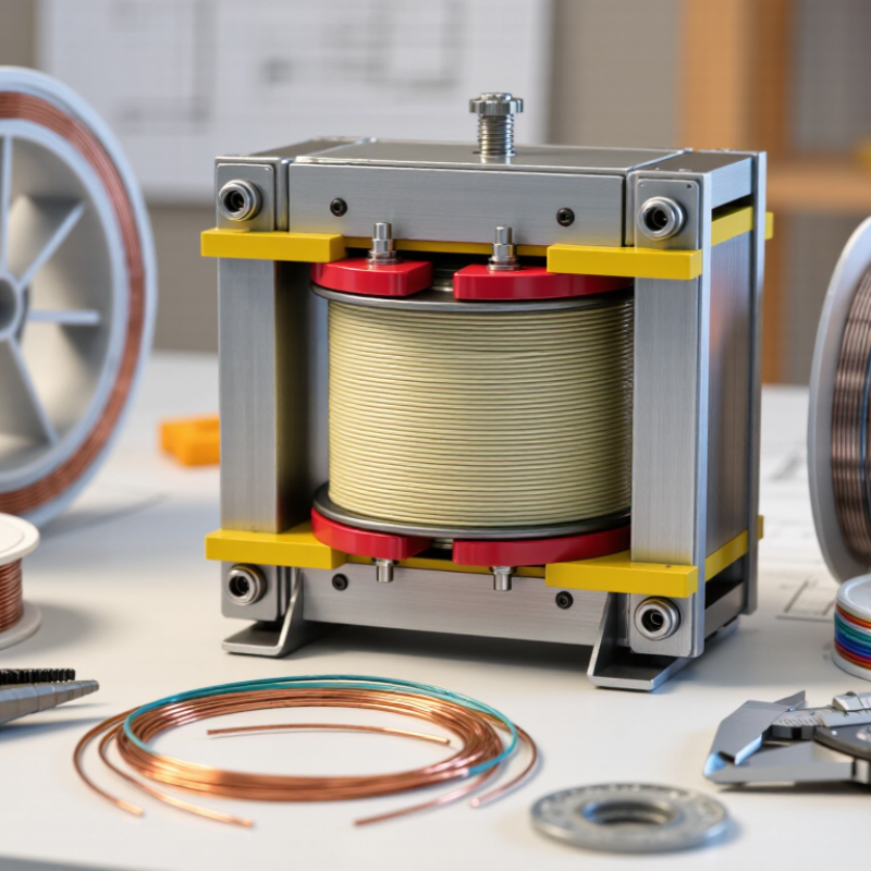
What Litz Wire Is and How Its Strands Reduce AC Loss
Litz wire is a bundle of many fine copper strands, each insulated from its neighbors. The strands follow a repeated transposition pattern, so each occupies different positions in the magnetic field. This helps distribute current more evenly and can reduce skin-effect and proximity-effect losses. Not automatically.
The IEC 60028 copper-resistivity reference corresponds to about 1.724 × 10⁻⁸ Ω·m at 20°C. Using that value, calculated copper skin depth is approximately 0.21 mm at 100 kHz and 0.066 mm at 1 MHz. These figures show why a thick, solid conductor may carry current unevenly at high frequencies. Skin depth is not a complete design rule, though; nearby windings and core geometry also affect AC resistance.
A practical design uses strand diameters suited to operating frequency, then checks the complete winding under realistic conditions. Fine strands alone do not guarantee lower loss. Poor transposition, excessive bundle diameter, or crowded turns can blunt the benefit. A useful reality check is measured winding temperature and impedance, not the wire specification alone. I would still verify the result in the finished assembly.
2026 Best Litz Wire for High Frequency Applications? — What Litz Wire Is and How Its Strands Reduce AC Loss
| Design factor | Typical range or example | How it affects performance | Selection guidance |
|---|---|---|---|
| Wire construction | Many individually insulated copper strands, gathered and transposed or braided into a bundle | Strand insulation and transposition help distribute current among strands and reduce the effects of skin and proximity currents. | Confirm that the construction is genuinely transposed; a simple bundle of insulated strands may not provide equivalent current sharing. |
| Copper skin depth at 20 kHz | Approximately 0.46 mm | Current tends to crowd toward the conductor surface as frequency rises, increasing AC resistance. | Use skin depth as a design reference, not as a guarantee of low loss; winding geometry and nearby magnetic fields also matter. |
| Copper skin depth at 100 kHz | Approximately 0.21 mm | Thinner strands can reduce current crowding within each strand at this frequency. | Compare strand diameter with the operating-frequency skin depth, then verify losses under the actual waveform and winding conditions. |
| Copper skin depth at 1 MHz | Approximately 0.066 mm | At this frequency, relatively small strand diameters may be needed to limit skin-effect losses within individual strands. | Very fine strands can increase insulation fraction, handling difficulty, and cost. Check both electrical and mechanical requirements. |
| Strand diameter | Common designs use strands from tens to several hundred micrometres; the suitable value depends on frequency and construction. | Smaller strands can reduce strand-level skin effect, but do not by themselves eliminate proximity effect or other AC losses. | Choose strand size with the frequency spectrum, current, bundle size, and winding-field distribution in mind. |
| Number of strands | From a few dozen to several thousand, depending on total copper area and strand size | More strands can provide the required copper area while keeping each strand small, but may make the bundle larger and harder to terminate. | Specify total copper cross-sectional area as well as strand count; strand count alone is not a measure of current capacity. |
| Common applications | High-frequency transformers, inductors, resonant converters, wireless-power coils, and induction-heating equipment | These applications can have significant AC resistance due to high frequency, strong magnetic fields, or both. | Consider litz wire when measured or modeled AC losses justify its added complexity; it is not automatically the best choice for every high-frequency winding. |
| Insulation and termination | Strand enamel, bundle wrapping, and application-specific end preparation | Insulation affects bundle fill, voltage capability, thermal behavior, and the reliability of electrical connections. | Check temperature class, voltage requirements, winding space, and the required stripping or soldering process before selecting a construction. |
| Thermal and loss verification | Evaluate at the intended frequency, waveform, RMS current, winding layout, and operating temperature | Litz wire can reduce some AC losses, but total loss also includes copper DC resistance, proximity effect, core loss, and connection losses. | Use an appropriate loss model or prototype measurement, and verify temperature rise in the final assembly. |
Copper skin-depth values are approximate at about 20°C and assume a sinusoidal field; actual performance varies with temperature, waveform, strand insulation, transposition, and winding geometry. There is no single litz-wire specification that is best for every high-frequency application.