SunVena Solar Blog

Residential Solar News, Insights & Resources

10 Best Energy Discharge Capacitors for Global Buyers

Choosing an Energy Discharge Capacitor is not just a matter of comparing capacitance values. Buyers must match the component to the pulse energy, peak voltage, discharge rate, and repetition frequency of their equipment. A capacitor that looks suitable on paper may overheat or wear prematurely under real operating conditions. Small details matter.

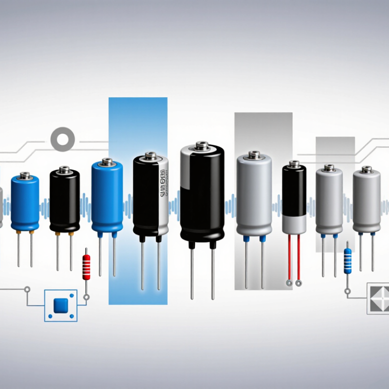
This guide introduces ten options for global buyers, including products intended for industrial systems, test equipment, and other pulsed-power applications. It considers practical specifications such as capacitance tolerance, equivalent series resistance, temperature range, expected service life, and terminal design. A compact unit may fit a tight enclosure, while a larger model may offer stronger thermal performance. Neither is automatically the better choice.

Reliable selection depends on more than a product listing. Review the manufacturer’s datasheet, application notes, and stated test conditions, then confirm that the values match your circuit and operating environment. Check availability, lead times, technical support, and documentation with the supplier as well. These can vary by region and distributor. A ranking cannot replace engineering review, and specifications may change over time. That is worth remembering. The ten products in this overview offer a starting point, not a universal verdict; careful comparison with your system requirements remains essential.

10 Best Energy Discharge Capacitors for Global Buyers

How Energy Discharge Capacitors Store and Release Electrical Energy

Energy Discharge Capacitors for Global Buyers: How They Store and Release Electrical Energy

An energy discharge capacitor stores electrical energy between two conductive plates, separated by an insulating dielectric. During charging, one plate accumulates positive charge while the other gains negative charge. The dielectric prevents direct current from crossing the gap. Energy rises with capacitance and the square of voltage, described by E = ½CV². A small voltage increase can therefore produce a substantial energy increase. Keep that in mind.

When a switching circuit connects the capacitor to a load, stored charge flows through the circuit as a brief, high-current pulse. The pulse may power a flash, actuator, or other equipment requiring rapid energy delivery.

Real performance depends on more than capacitance. Engineers check rated voltage, pulse duration, equivalent series resistance, and operating temperature against the application. Low resistance can reduce heat during discharge, but wiring and circuit layout also affect pulse behavior. Repeated charging and discharging can cause heating and gradual wear, so test conditions matter.

A component’s printed rating is not a complete design review. That detail is easy to overlook. In practical systems, a controlled discharge path and suitable protective components help manage residual voltage after power is removed.

Always verify the design with qualified testing; stored energy can remain hazardous even when equipment appears switched off.

Key Specifications for Comparing Energy Discharge Capacitors

A useful comparison starts with capacitance and rated voltage, but neither figure tells the whole story. Stored energy is calculated as E = ½CV², so a 100-microfarad capacitor charged to 2,000 volts stores about 200 joules. That estimate is useful, not a complete design check. Confirm the permitted voltage, polarity, and discharge conditions in the technical data.

Peak discharge current, equivalent series resistance, and inductance affect how quickly energy reaches a load. For a short pulse, even small internal resistance can create heat and reduce delivered current. Check the specified waveform, pulse duration, and repetition rate; two capacitors with similar ratings may behave differently under repeated firing. Numbers need context. Ask for test conditions when a datasheet is unclear.

Temperature range, expected service life, terminal design, and physical dimensions matter in real installations. Inspect how the part will be mounted, cooled, and connected, especially where vibration or tight spacing is present. Allow voltage and thermal margins rather than designing at the stated limit. A detail I would revisit is the assumed pulse rate: actual operating cycles can exceed early estimates, changing both heating and lifetime. Compare tolerances and insulation requirements against the equipment environment before choosing a part.

Ten Energy Discharge Capacitors for Global Buyers

Ten Energy Discharge Capacitors for Global Buyers

A practical shortlist includes metallized polypropylene pulse-film, oil-impregnated power, ceramic pulse, high-voltage ceramic, aluminum electrolytic, DC-link electrolytic, polypropylene snubber, pulse-forming-network, mica pulse, and supercapacitor designs. Each serves a different discharge profile. Details matter. Film types often suit repeatable pulses, while electrolytics can store substantial energy but may be less suited to extreme peak currents. Ceramics offer compact construction, yet capacitance can fall under applied voltage.

Compare rated voltage, capacitance, equivalent series resistance, peak current, pulse width, repetition rate, and cooling conditions. Ask suppliers for waveform-specific test data, not just a headline energy figure.

The International Energy Agency’s 2024 Batteries and Secure Energy Transitions report says battery storage additions reached about 42 GW in 2023, more than double the previous year. That growth highlights why fast-response capacitors may complement batteries in power-conversion systems, though the technologies are not interchangeable.

A shortlist is never universal. Humidity, vibration, service access, and operating temperature can change the choice. I would also leave margin for aging; the exact margin depends on the duty cycle and available maintenance.

How to Select a Capacitor for Your Application and System

10 Best Energy Discharge Capacitors for Global Buyers

Choosing a capacitor for an energy discharge system starts with the pulse, not the catalog. Define the required energy, voltage range, pulse duration, and repetition rate. Capacitance alone is not enough. Check peak current, equivalent series resistance, and equivalent series inductance against the circuit’s demands. A low-resistance part can reduce heating, but it may also change the discharge waveform. That trade-off deserves a bench test.

Tips: Confirm the maximum operating voltage, including transients. Compare pulse ratings at your actual temperature and repetition rate. Check dimensions and terminal spacing before ordering. Small details matter.

Then assess service life, capacitance tolerance, leakage current, and cooling conditions. A capacitor mounted near a warm power component may behave differently from one tested on a cool bench. Review the datasheet’s test conditions, and ask for supporting data when pulse performance is unclear. Prototype measurements can reveal overshoot or heating that calculations miss. This step can feel slow, but skipping it is often more costly. Recheck the complete system after installation; wiring inductance and layout can alter the pulse even when the capacitor meets its specification.

10 Energy-Discharge Capacitor Configurations for Global Buyers

Illustrative capacitor-bank examples compared by calculated stored energy.

Stored energy is calculated as E = ½CV² using the capacitance and rated voltage shown in each label. These examples are not product rankings or application prescriptions. Usable pulse energy depends on the discharge voltage range, circuit resistance, pulse duration, temperature, and capacitor limits.

Global Sourcing, Safety Standards, and Supplier Evaluation

Energy-discharge capacitors must match the actual duty cycle, not just the headline voltage. Check capacitance, pulse current, equivalent series resistance, temperature range, and expected service life. A capacitor used for repeated pulses may face different thermal stress than one used occasionally. Details matter. Request datasheets and test reports for the exact part number and revision, not a similar product.

Tips: Before ordering, share the operating voltage, pulse profile, ambient temperature, and mounting conditions with suppliers. Ask for evidence. Confirm that certificates and safety documentation apply to the destination market and intended use; requirements vary by region and product category. Never treat a generic compliance statement as proof that every configuration is covered.

Evaluate suppliers on traceability, production consistency, and clear technical support. Ask how they control incoming materials and final testing, and whether samples can be assessed under your real operating conditions. Compare lead times and packaging as well as price, since moisture, vibration, or rough handling can affect components in transit. A low quote may look attractive, but incomplete records or vague answers can create costly delays. One easy mistake is approving a sample without checking whether production units will use the same specifications and inspection criteria. Keep the decision evidence-based, and record any assumptions that still need verification.

10 Best Energy Discharge Capacitors for Global Buyers – Global Sourcing, Safety Standards, and Supplier Evaluation

This shortlist compares ten capacitor technologies and configurations used for energy storage and controlled discharge. The examples are technology categories, not specific products or performance guarantees. Actual ratings depend on the design, operating conditions, and supplier qualification data.

Option Capacitor type / construction Typical design range Illustrative stored energy Common use and advantages Key limitations and safety checks Standards and supplier evaluation
1. High-energy polypropylene pulse capacitor Polypropylene film, commonly wound or stacked; designed for repetitive pulse service. Custom designs span low microfarads to hundreds of microfarads, with rated voltage selected for the application, often from hundreds of volts to several kilovolts. 100 µF at 10 kV stores 5 kJ. Suitable for pulsed power, test equipment, and energy-transfer circuits. Polypropylene generally offers low dielectric loss and good pulse performance. Confirm peak current, pulse width, repetition rate, reversal capability, cooling, and end-of-life behavior. Do not infer pulse ratings from capacitance and voltage alone. Ask whether IEC 61071 or UL 810 applies to the offered design and request relevant qualification reports. Compare pulse-life and thermal-test conditions.
2. Film-foil high-current pulse capacitor Separate metal-foil electrodes with film dielectric; engineered for high peak-current discharge. Often selected in the microfarad-to-hundreds-of-microfarads range; voltage and current ratings are design-specific. 20 µF at 20 kV stores 4 kJ. Useful where high peak current and low equivalent series resistance are priorities, such as pulse forming and discharge circuits. May be larger than metallized designs and can require carefully designed busbars and terminals. Verify current waveform, inductance, and connection forces. Request measured ESR/ESL, peak-current limits, and pulse-life data. Confirm applicable IEC 61071 or UL 810 scope rather than assuming certification.
3. Low-inductance laminated film capacitor Flat or laminated polypropylene film construction with broad, short current paths and low-inductance terminals. Typically engineered for high-current, fast-edge applications; capacitance and voltage are specified to suit the circuit. 50 µF at 1 kV stores 25 J. Can reduce parasitic inductance in switching, clamping, and fast-discharge assemblies. Often easier to integrate close to a bus or switching device. Mechanical layout and terminal geometry materially affect performance. Check allowable ripple current, temperature rise, and mounting requirements. Evaluate the complete assembly, not just the capacitor element. Request dimensional drawings, current-path details, and applicable power-capacitor test evidence.
4. High-voltage oil-impregnated pulse capacitor Film dielectric in a sealed enclosure, with an impregnant chosen by the manufacturer for insulation and thermal performance. Usually application-specific, ranging from kilovolt-class units to custom high-voltage assemblies. 100 µF at 15 kV stores 11.25 kJ. Can be considered for high-voltage pulse applications where insulation design and energy density are important. Confirm fluid composition, sealing, orientation limits, leakage controls, environmental restrictions, and transport classification. Require safe discharge and handling instructions. Request dielectric-fluid and environmental declarations, routine-test records, and applicable safety approvals for the destination market.
5. Power-electronic DC-link film capacitor Metallized polypropylene film, commonly in cylindrical or rectangular modules for DC-bus service. Commonly available from tens of microfarads to several millifarads; voltage classes vary by system and design. 1,000 µF at 800 V stores 320 J. Used in converters, inverters, and industrial drives. Low losses and self-healing behavior are advantages in suitable designs. A DC-link rating does not automatically qualify a part for high-energy pulsed discharge. Check discharge current, ripple current, voltage transients, and fault behavior. IEC 61071 is relevant to many power-electronic capacitors. Request ripple-current curves, thermal data, lifetime model assumptions, and safety documentation.
6. High-voltage ceramic pulse capacitor Ceramic dielectric construction; capacitance and voltage behavior depend strongly on dielectric class and design. Often used at relatively low capacitance and high voltage; available values vary widely by dielectric and geometry. 1 µF at 5 kV stores 12.5 J. Compact option for high-voltage pulse, snubber, and discharge circuits where suitable capacitance is available. Check capacitance change with voltage and temperature, dielectric losses, mechanical stress sensitivity, and pulse-current limits. Ask for the applicable IEC 60384 specification, voltage-dependent capacitance data, and pulse-test results for the intended waveform.
7. Metallized polyester film capacitor Metallized PET film construction; general-purpose film technology that may be offered in selected discharge designs. Typically considered for moderate-energy, moderate-frequency applications; voltage and pulse capability are product-specific. 10 µF at 1 kV stores 5 J. Can offer a compact, cost-conscious solution for less demanding energy-storage or discharge circuits. Generally not a direct substitute for polypropylene in demanding high-frequency or high-repetition pulse service. Verify dielectric heating and lifetime at actual conditions. Request dielectric and endurance-test information, including temperature and waveform conditions. Verify the relevant product specification and approvals.
8. Screw-terminal aluminum electrolytic capacitor bank Multiple polarized aluminum electrolytic capacitors connected in series and/or parallel, with balancing and protection as required. High capacitance at comparatively lower voltage per unit; complete bank ratings depend on series/parallel design and operating temperature. A 10 mF bank at 450 V stores about 1.01 kJ. Useful when high capacitance is needed in power supplies, braking systems, or moderate-voltage energy storage. Observe polarity, surge limits, ripple-current ratings, balancing, venting, aging, and discharge time. Series-connected units may require voltage-sharing measures. Check applicable IEC 60384 product specifications and destination-market approvals. Request bank-level balancing, fault, and thermal documentation.
9. Electric double-layer capacitor (supercapacitor) module Series/parallel EDLC cells with balancing, monitoring, and protective components as required. Cell voltage is low relative to conventional power capacitors; modules combine cells to meet system voltage and energy requirements. A 10 F module at 48 V stores 11.52 kJ. High stored energy and many charge/discharge cycles can suit backup, regenerative, and short-duration power applications. Terminal voltage varies substantially during discharge. Check balancing, maximum current, temperature limits, leakage, short-circuit protection, and service life. IEC 62391-1 covers fixed electric double-layer capacitors for electronic equipment. Request module-level safety, balancing, and cycle-life evidence.
10. Engineered capacitor bank with discharge and protection hardware Matched capacitor units assembled with busbars, enclosure, monitoring, and, where required, discharge resistors or switching components. Custom; rated voltage, capacitance, stored energy, and discharge profile are specified for the complete assembly. A 1 mF bank at 2 kV stores 2 kJ. Provides a system-level option when standard single capacitors cannot meet the required energy, voltage, footprint, or service configuration. Assess voltage sharing, fault containment, clearances, creepage, residual voltage, interlocks, and verified discharge time. A resistor alone does not prove that a bank is safe to handle. Request assembly drawings, risk and safety documentation, acceptance-test records, and market-specific conformity evidence. Confirm that tests cover the complete bank.
Illustrative stored energy uses E = ½CV², where E is joules, C is farads, and V is volts. Values are calculations for the stated examples, not product ratings. Standards applicability depends on the product design and intended use.

Global sourcing checklist: Compare guaranteed ratings under the same waveform, temperature, mounting, and lifetime conditions. Request datasheets, drawings, traceability, production-test records, applicable conformity documents, packaging and transport details, and written confirmation of the offered discharge and safety limits. Before servicing any capacitor system, isolate it, follow the manufacturer’s discharge procedure, and verify residual voltage with suitable equipment.